building a tri planar projection in cops (opencl)
Before diving in I just want to mention that this tutorial is a little more on the technical side and mainly serves as an introduction for how to build a tool using opencl within the context of cops. You can do a lot in cops without writing a single line of code, but it does definitely open some doors!
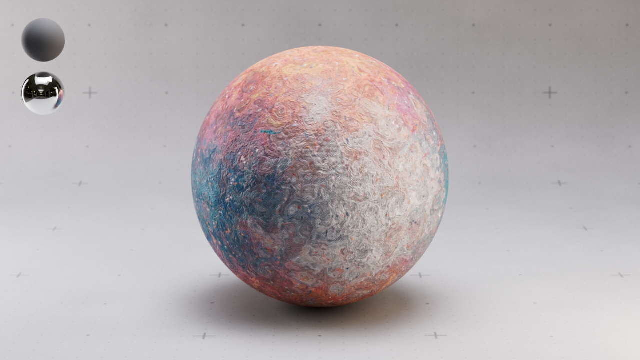
Tri planar projections are a useful technique for projecting textures without visible seams. Since there’s no native tri planar in Copernicus (as of houdini 20.5), we have a good excuse to build our own. This could be done using vex or a large network of native cops nodes, however processing speed makes opencl preferable.
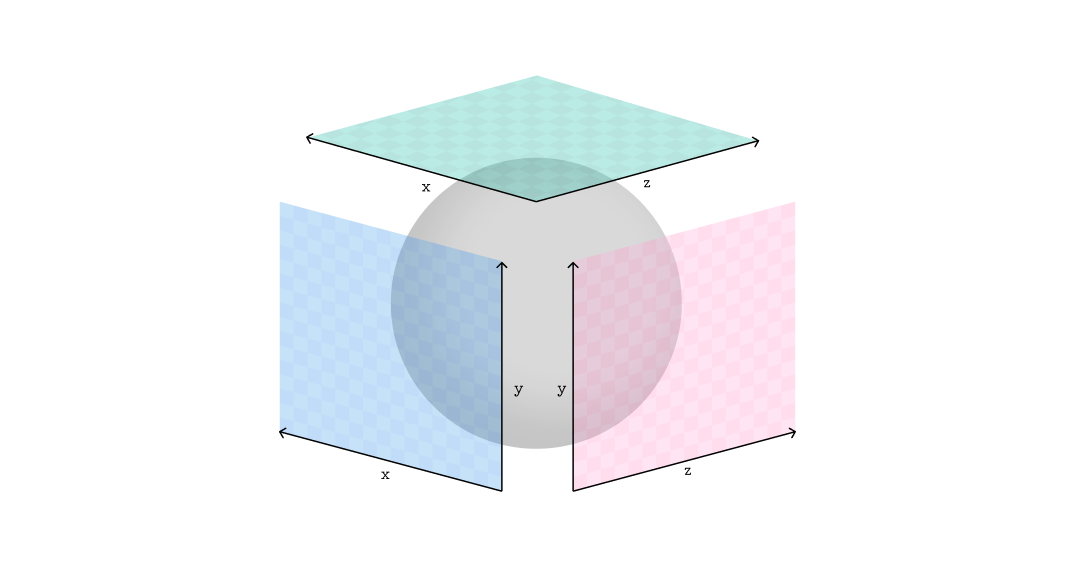
A tri planar projection is a set of 3 parallel projections, xy, zy and zx, blended based on their respective facing ratios. Knowing this, the steps of our process will be:
- calculate blending weights using normals
- sample textures for each projection plane
- blend textures using weights
initial setup
First, a quick bit of set up. Create the following network and link or create your geometry in the sop import, uv’s and normals are required on the geometry.
- On the Rasterize Setup, set space to UVs
- On the wrangle, change the type of the first input to Geometry, then add RGB inputs named origP and N
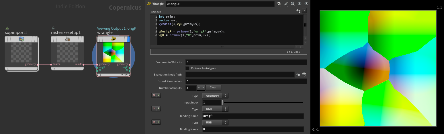
Fill the wrangle with this vex snippet:
int prim;
vector uv;
xyzdist(1,v@P,prim,uv);

v@origP = primuv(1,"origP",prim,uv);
v@N = primuv(1,"N",prim,uv);
This process just maps your position and normal data to uv space so we can map 3D elements in cops. Using the xyzdist function does a great job of extrapolating the values at uv boundaries so we don’t have to worry about seams.1
Add an opencl node and replace the kernel code with the following:
#bind layer !&Cdout float3

#bind layer origP? float3
#bind layer N? float3

@KERNEL
{
    @Cdout.set(@origP);
}
Finally there’s a couple of steps to access the data from our wrangle in opencl.
- Select spare parameters button
- Remove src and dst under the signature tab
- Connect origP and N from wrangle
blending weights
We need to calculate the facing ratio of the surface in relation to x, y and z, then store this as 3 weights. This could be done using a dot product but it’s more efficient to just use the individual components of N, this works as long as N is normalised. For example, dot((float3){1.0f, 0.0f, 0.0f}, N) will produce the same result as N.x.
The result of this ranges from 1 (facing) to -1 (facing away), the weights need to be in a positive range so a fabs function can be used to get absolute values. Putting this together for x comes the following:
#bind layer !&Cdout float3
#bind layer origP? float3 val=0
#bind layer N? float3 val=0
float3 N, weight;
@KERNEL
{
N = normalize(@N);
weight.x = fabs(N.x);
@Cdout.set(weight);
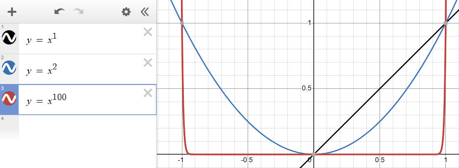
}We want some way to control the falloff of the blending, one method for this is raising our facing ratio to a power. To do this, bind a float parameter named exponent (feel free to give this a more intuitive label).2
#bind parm exponent float val=1.0Then raise N.x to the exponent:
weight.x = pow(fabs(N.x), @exponent);
The limits to set your exponent parameter at are arbitrary, something like 1 - 100 works fairly well.
Now we can add the weights for y and z, visualing the output of weight directly works well for debugging at this stage.
@KERNEL
{
    N = normalize(@N);

    weight.x = pow(fabs(N.x), @exponent);
    weight.y = pow(fabs(N.y), @exponent);
    weight.z = pow(fabs(N.z), @exponent);

    @Cdout.set(weight);
}
The weights need to sum to 1 so the current set up only works for an exponent of 2. Squaring works because calculating the sum of the squared components is the same as performing a dot product with itself, and the dot product of a unit vector with itself is always 1.
To make the blend work for exponents other than 2, we divide weight by the sum of weights:
weight /= weight.x + weight.y + weight.z;
Putting all this together should give nice control over the blending.
projecting textures
First we need to bind inputs for our textures, I named these textureZY, textureXZ and textureXY. This binding process is the same as we did for origP and N.
Finding the coordinates for the projections and sampling the texture are fairly straight forward. The coordinates are found by taking the relevant components from origP, then these coordinates are used by the textureSampleRect function.
uv = @origP.zy;
col = @textureZY.textureSampleRect(uv, @dPdxy.texture)
The first parameter of textureSampleRect is used to input the centre of the sample area, the second refers to the size of the sample area. @dPdxy is a default binding that returns the size of the current output buffer element in image space.3
Now just sample the textures for the other 2 planes, then blend by by multiplying the texture by the relevant weight, using addition assignment to add this to col.
//zy plane
uv = @origP.zy;
col = @textureZY.textureSampleRect(uv, @dPdxy.texture) * weight.x;

//xz plane
uv = @origP.xz;
col += @textureXZ.textureSampleRect(uv, @dPdxy.texture) * weight.y;

//xy plane
uv = @origP.xy;
col += @textureXY.textureSampleRect(uv, @dPdxy.texture) * weight.z;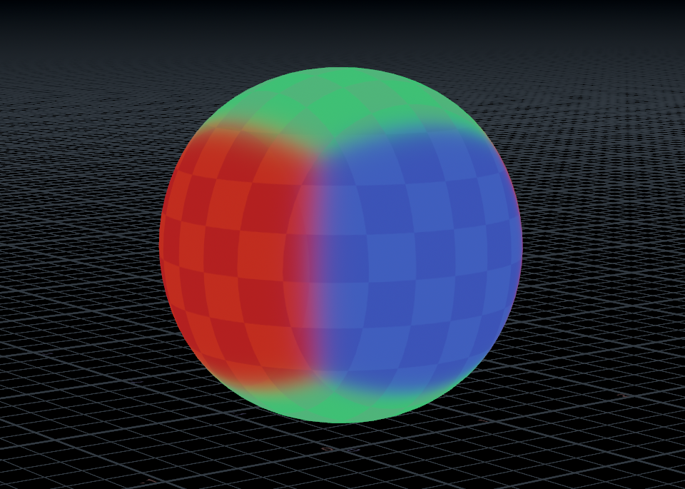
That’s pretty much it for the opencl side of things, here’s the complete code:
#bind layer !&Cdout float3
#bind layer origP? float3 val=0
#bind layer N? float3 val=0
#bind layer textureZY? float3 val=0
#bind layer textureXZ? float3 val=0
#bind layer textureXY? float3 val=0
#bind parm exponent float val=2
float2 uv;
float3 col, N, weight;
@KERNEL
{
N = normalize(@N);
weight.x = pow(fabs(N.x), @exponent);
weight.y = pow(fabs(N.y), @exponent);
weight.z = pow(fabs(N.z), @exponent);
//normalise weights
weight /= weight.x + weight.y + weight.z;
//zy plane
uv = @origP.zy;
col = @textureZY.textureSampleRect(uv, @dPdxy.texture) * weight.x;
//xz plane
uv = @origP.xz;
col += @textureXZ.textureSampleRect(uv, @dPdxy.texture) * weight.y;
//xy plane
uv = @origP.xy;
col += @textureXY.textureSampleRect(uv, @dPdxy.texture) * weight.z;
@Cdout.set(col);
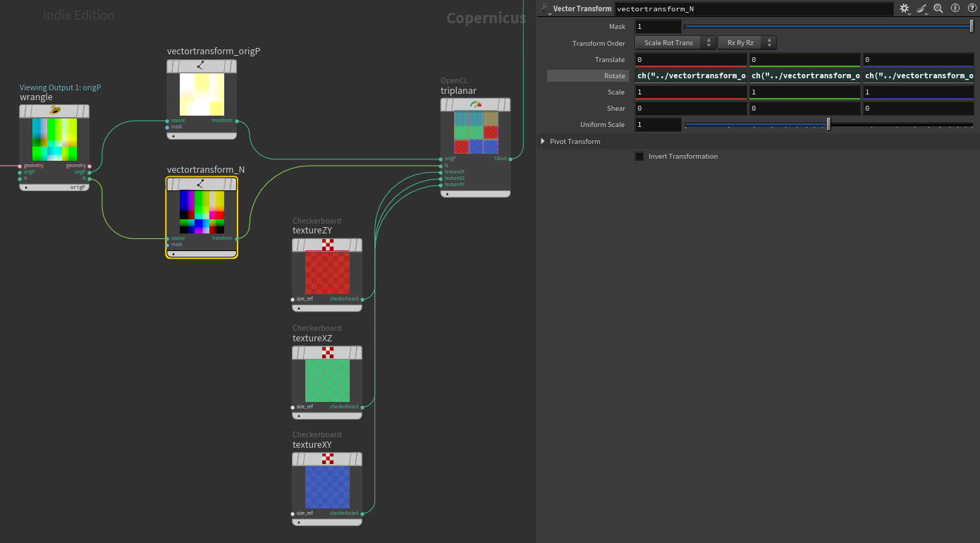
}transforming projections
Using vector transforms on origP and N will allow you to transform the projection. Just make sure the rotations are linked.
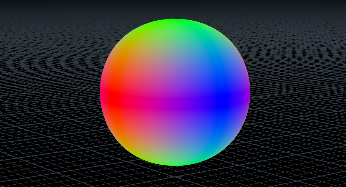
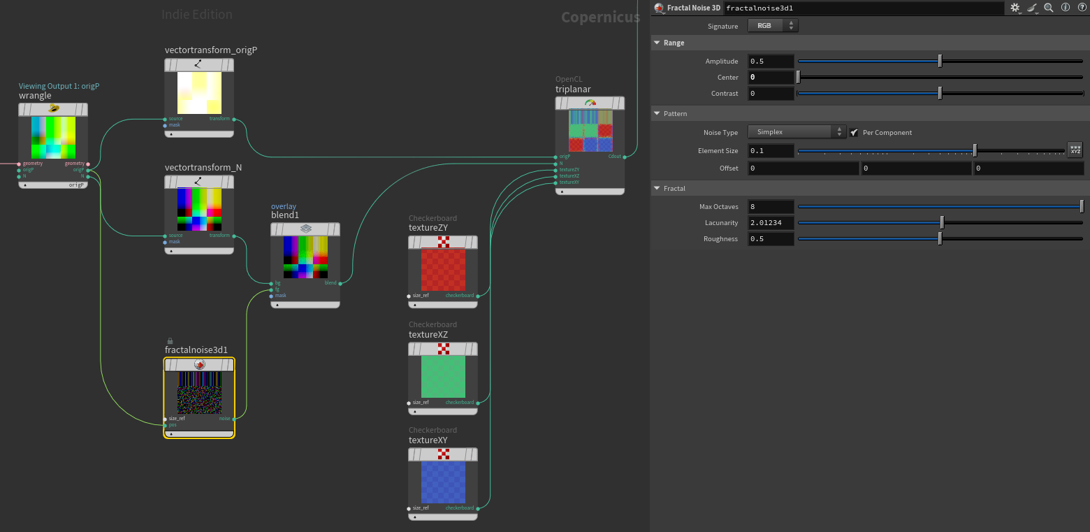
breaking up the blend
Overlaying a 0 centred RGB noise over N provides a nice breakup on the blend. Similar techniques were used for the feature image for this tutorial.
notes
The result of this tutorial is a very basic tri planar projection, it could be further extended to support normal maps, correct mirrored projections on reverse faces and more. Also if many of the same projection with different textures are required, it could make sense to only output uv’s and blending masks, That way the textures could be sampled after the tri planar node and the blending masks would only be calculated once.
I’m still fumbling my way through a lot of this myself so if anything could be made simpler, faster or easier to understand please let me know!
-
Thanks to Rohan Dalvi for sharing this technique from Falcón Saavedra Rasterize attributes using VEX in COPs ↩
-
Jasper Flick’s triplanar tutorial for unity covers exponentiation to control blending Triplanar Mapping in Unity ↩
-
Lots of great information in the SideFX documentation, including default bindings such as @dPdxy OpenCL for VEX users ↩